

Task1 – Literature Review
Accelerated bridge construction (ABC) has recently become common due to its numerous advantages such as minimizing traffic delays and road closures, as well as reducing the construction time and efforts. ABC relies heavily on prefabricated reinforced concrete members. Connections of prefabricated members are particularly critical in moderate and high seismic zones because earthquake forces place high demand on nonlinear deformation capacity of adjoining members. Structural integrity of the bridge has to be maintained by capacity protected connections that experience no or little damage. Various connections have been explored in the past few years. These connections can be placed in two categories of coupler and pocket connections. Promising results have been obtained for different versions of both categories, although much research and development have to be done before reliable and proven design methods of the type used in practice can be recommended.
One of the methods to connect prefabricated bridge columns to footings is pocket connections. This research project concentrates on these types of connections as they have shown promising results while not violating the current AASHTO and Caltrans ban on couplers. Innovation concepts of this research project are as follows:
- Precast column and footing with pocket connection
- Post-tensioning using unbonded carbon fiber reinforced polymer (CFRP) tendons
- Ultra-high performance concrete (UHPC) in plastic hinge zone
This study focuses on a precast square column that is post-tensioned with unbonded carbon fiber reinforced polymer (CFRP) tendons and is connected to the footing using a pocket connection. Specific objectives of the project are to determine:
- the seismic performance of pocket connection with unbonded post-tensioned square column,
- the appropriate embedment length of square precast columns in pocket connections
- the effectiveness of CFRP tendons in minimizing residual displacements under strong earthquakes,
- the optimized level of PT force based on column geometric and strength characteristics
- the performance of ultra-high performance concrete (UHPC) in plastic hinge zone of square columns, and
- design considerations and methods for connections, CFRP PT columns, precast columns, and UHPC in plastic hinges.
Task2 – Preliminary Design of Single-Column Bent
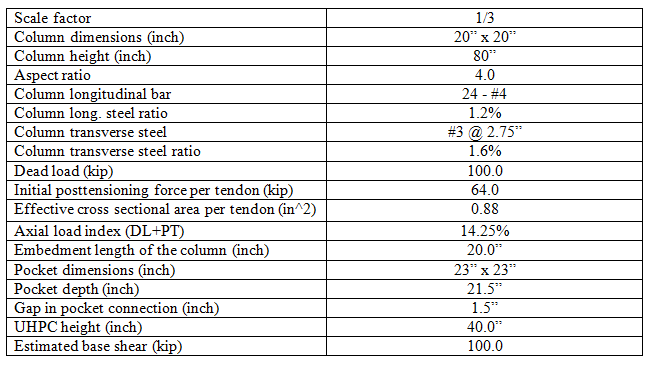
To accomplish the objectives of the study, a 1/3 scale of a square bridge column was designed according to AASHTO Guide Specifications for LRFD Seismic Bridge Design for a location in down town Los Angeles, CA. Figures 1-3 show the geometry and cross section of the column as well as footing details. The properties of the column is given in Table 1.

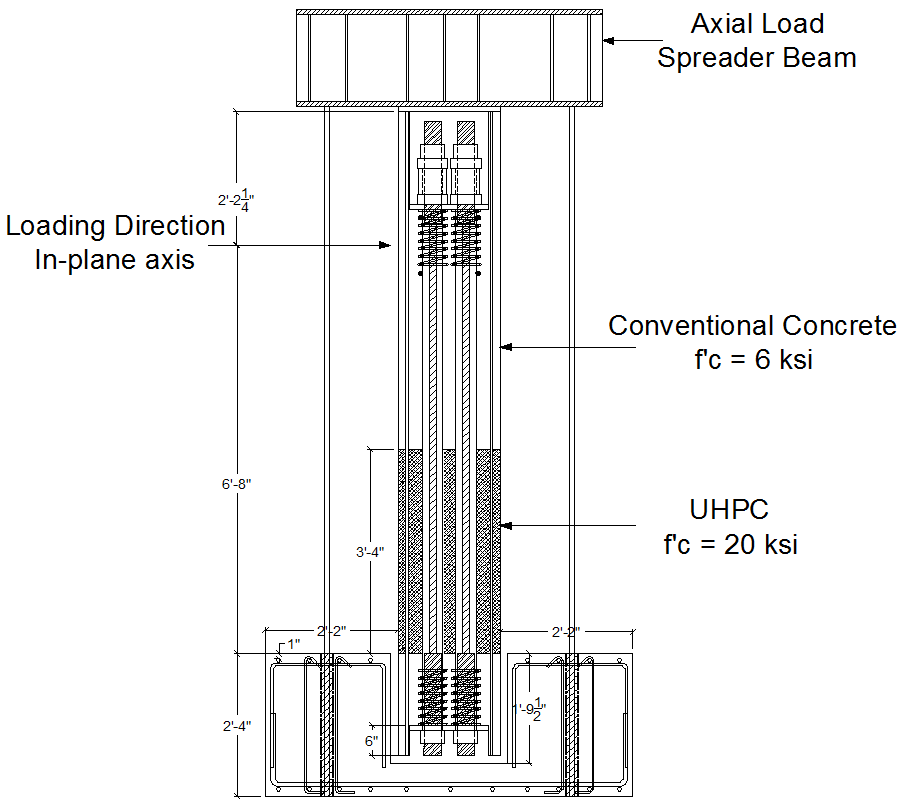
Figure 1. Geometry of the column
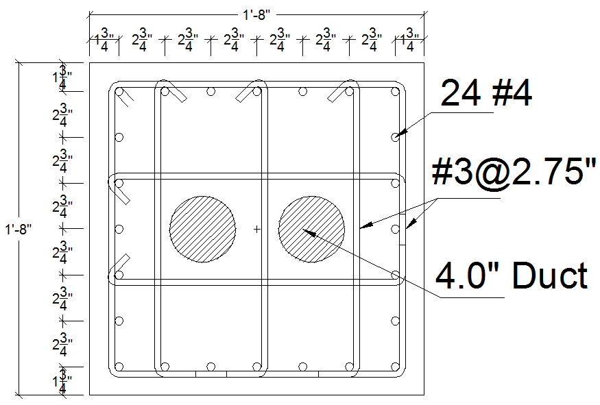
Figure 2. Cross section of the column

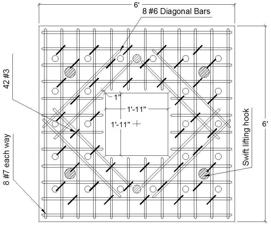
Figure 3. Footing details
Table 1. Properties of the column

Task3 – Pretest Nonlinear Finite Element Analysis of Pier Model for Single Column Bent
Static pushover analysis was conducted for the column model to determine its nonlinear behavior under lateral loading. Figure 4 shows the calculated pushover curve of the column model. The estimated drift capacity of the column is 8%, and the failure is due to longitudinal bar ruptures. Figure 5 shows the axial load variation of the column due to elongation of CFRP tendons during pushover analysis. According to Figure 5, the axial load in CFRP tendons increased approximately by 350% compared to the initial posttensioning force. Figure 6 shows stress-strain relationships of CFRP tendons during pushover analysis. The guaranteed capacity of CFRP tendons is 306 ksi. Under 8% drift, tendons reached 90% of this limit and did not fracture.

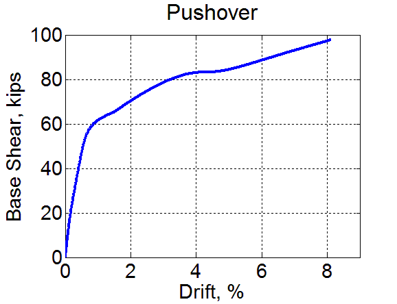
Figure 4. Pushover curve of the column model

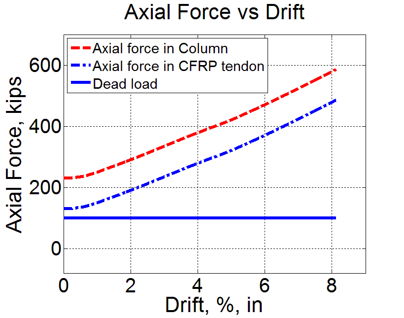
Figure 5. Axial load variation of the column and CFRP tendons

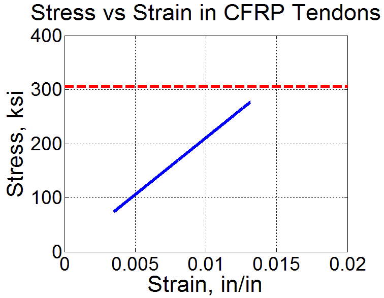
Figure 6. Stress-strain relationship of CFRP tendons
Nonlinear response history analysis was conducted to the column model for different near fault ground motions to investigate the effectiveness of the self-centering system in minimizing residual drifts. The analysis was performed for the novel column as well as two other identical conventional columns without posttensioning. As a representative response, the results of two ground motions, 1994-Northridge at Rinaldi station and 1978-Tabas, are represented. Figure 7 and Figure 8 show residual drifts vs. peak drifts for different levels of Rinaldi and Tabas earthquakes, respectively. According to the results, the residual drifts of the novel column for different levels of the earthquakes are almost zero.

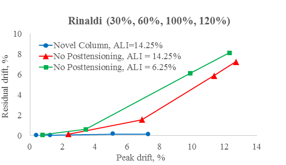
Figure 7. Residual drifts vs. peak drifts for different levels of Rinaldi earthquake

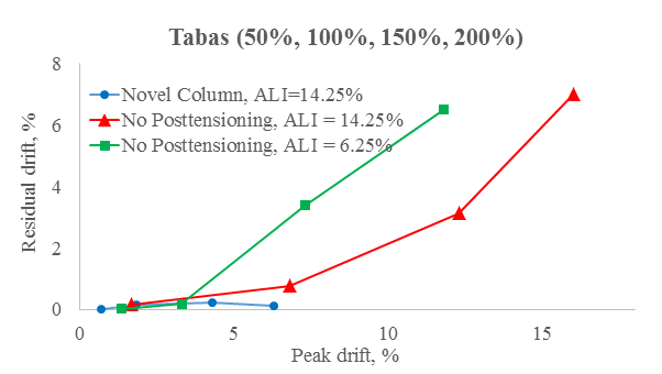
Figure 8. Residual drifts vs. peak drifts for different levels of Tabas earthquake
Task 4 – Construct the Test Models, Conduct Shake Table Tests, and Process Test Data
A 1/3 scale of a precast novel column model was constructed and posttensioned using CFRP tendons. UHPC, rather than concrete, is used in the plastic hinge zone. The novel column was inserted into the precast footing, which had a pocket in the middle for the column. Afterwards, UHPC was used to fill the gap between the column and the footing. Figure 9 shows a schematic representation of the test model. Figures 10-12 show CFRP tendons and anchorages, precast footing, and the final column model, respectively.
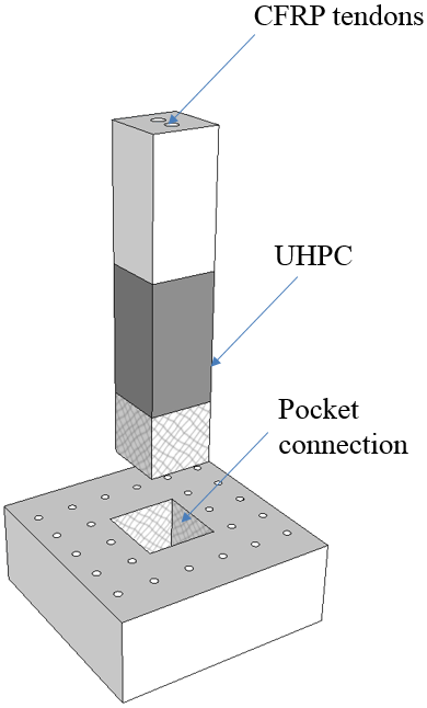
Figure 9. Schematic representation of the test model

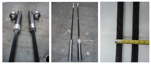
Figure 10. CFRP tendons and anchorages

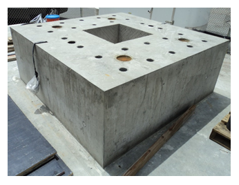
Figure 11. Precast footing with pocket area in the middle

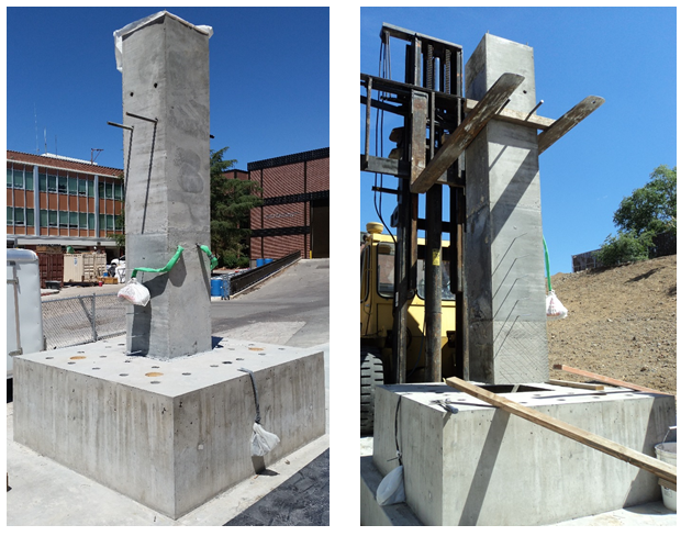
Figure 12. Insert precast column into the precast footing
The column will be tested on a shake table in July 2015 to evaluate its seismic performance under different levels of earthquakes. The record of the 1994-Northridge at Rinaldi station is selected for simulation in the shake table tests. Pretest analytical results have been promising. Shake table results will demonstrate if the predictions are accurate and will reveal necessary refinements in details and design.

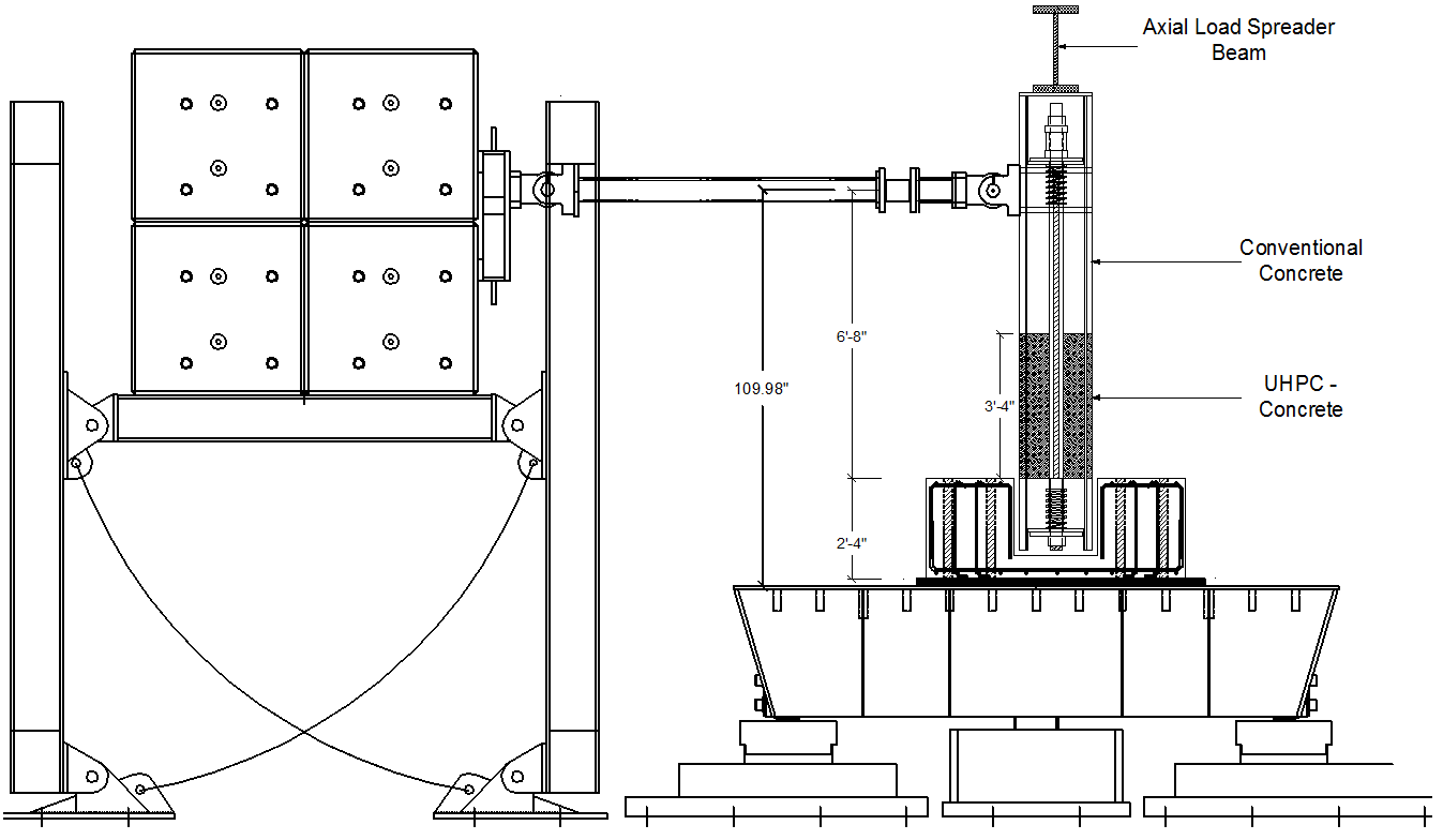
Figure 13. Shake table set up