

Task 1 – Literature Review
Through various resources within ABC-UTC, research team is familiar with existing ABC systems and projects. Nevertheless, a formal literature search carried out to identify different ABC project types, typical details, and documented problems and failures.
One common ABC system includes fabricating various elements offsite, transporting them to the site, and assembling the various pre-fabricated units on-site. The pre-fabricated elements can be deck modules, pile caps, abutments, approach slabs and intermediate bents. Many ABC bridges are built by constructing deck modules off sight. As they are assembled and set into place, a closure pour is installed to connect the adjacent modules. This in turn, results in a serviceability concern at the interface of the pour and the joint. Shrinkage and cracking can occur at the joint, as the deck concrete and pour concrete will have differing properties. Early identification of distress or damage at these locations can significantly reduce life cycle costs and maintain safety. Integral bridge abutments have also been constructed on ABC bridges. Inclusion of integral abutments eliminates bearings and expansion joints, which reduce maintenance costs and improve service life. A literature review has been initiated to identify issues associated with integral abutments that will need additional study. At this time, Integral abutments have been limited to relatively short span bridges with small skew angles. Two potential areas for additional research include:
Expanding the knowledge of integral bridge behavior into bridges with longer spans, curved or highly skewed alignments.
Looking for design alternatives/methodologies for the soil/structure interface at the integral abutments. This behavior is not well understood, and the soil deformation resulting from the cyclical bridge movements results in either a gap or heaving between the structure and the soil backfill that requires on-going maintenance.
Task 2 – National Survey
A short survey through AASHTO will be conducted to identify the ABC projects that are in service. Coordination made with other ongoing projects and possibly combine them in ord er to reduce time that different agencies have to spend on answering survey questions. While this survey has not yet been initiated, State DOT’s are aware of the data base and many have submitted data to the data base.
Task 3 – Categorizing the Available ABC Project Types
The identified ABC projects that are open to traffic will be divided into several categories. The number of categories will be decided based on results of tasks 1 and 2. This task is ongoing as the research progresses. One potential category includes methods to install an entire bridge with a single operation, such as lateral slides or other transport methods. Another category includes construction of pre-fabricated elements which are then assembled on site. These categories may be sub-divided as research continues, and other categories will likely be identified.
Task 4 – Site Visits and Documenting Service Life Performance of Select ABCProjects
Under this task, site visits conducted to inspect a select number of bridges within each category identified under Task 3. Visual inspection, together with review of available design and maintenance documents, will be carried out to identify and document the service life performance of bridges. Attempts will be made to identify the possible causes of any observed service life issues. As noted above under Task 1 Literature Review, closure pours have been identified as having potential service life issues. The literature review has identified a number of typically specified details (Dickinson, et.al., 2014). A better understanding of the behavior and performance of closure pours can be provided by non-destructive testing such as Impulse Response (IR) testing. This method is becoming a tool to assist in evaluation of structures, including bridges. IR tests will assist in clarifying the factors that reduce the effectiveness of closure pour, which in turn leads to developing strategies to mitigate these factors. IR testing has been used to identify high mobility (low-stiffness) areas associated with damage such as honeycombs, voids and cracks in concrete structures. The method can be used for a quick and detailed evaluation of structural conditions (Olson Instruments, 2008). The service life of ABC bridges can be increased with this understanding and by developing details that could provide better service life performances. A test program was developed to investigate IR signatures on existing ABC bridge structures and laboratory test specimens. Site visits and a non-destructive testing program have been carried out at two bridge sites to date. Field IR testing has been completed on 2 bridges. The 2 bridges selected for this study, designated as bridge A and Bridge B, have differing closure pour details. The longitudinal pour on Bridge A is about 12-inches wide. The reinforcing steel extending out of the pre-fabricated module has heads on the end of the bars to increase pull out resistance. The closure pour detail for Bridge B included “hairpin” shaped reinforcing steel loops extending from the deck modules. Longitudinal rebar was then threaded thru the loops, and the joint was poured with ultra-high strength concrete. The pour was only about 6-inches wide. The IR test results show increased mobility with increasing distance from the supporting girders. The mobility plots appear to be symmetric around the center line of the closure pour. The plots also appeared to have smooth curves, possibly indicating the closure pour is behaving as a continuous unit with the adjacent module. The actual mobility values were normalized with mobility values obtained by finite element methods.
Bridge A Results:

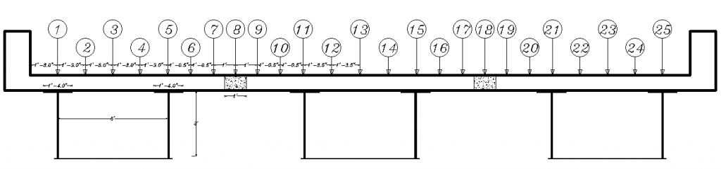
Figure 1. Node Location on the section of the bridge A.

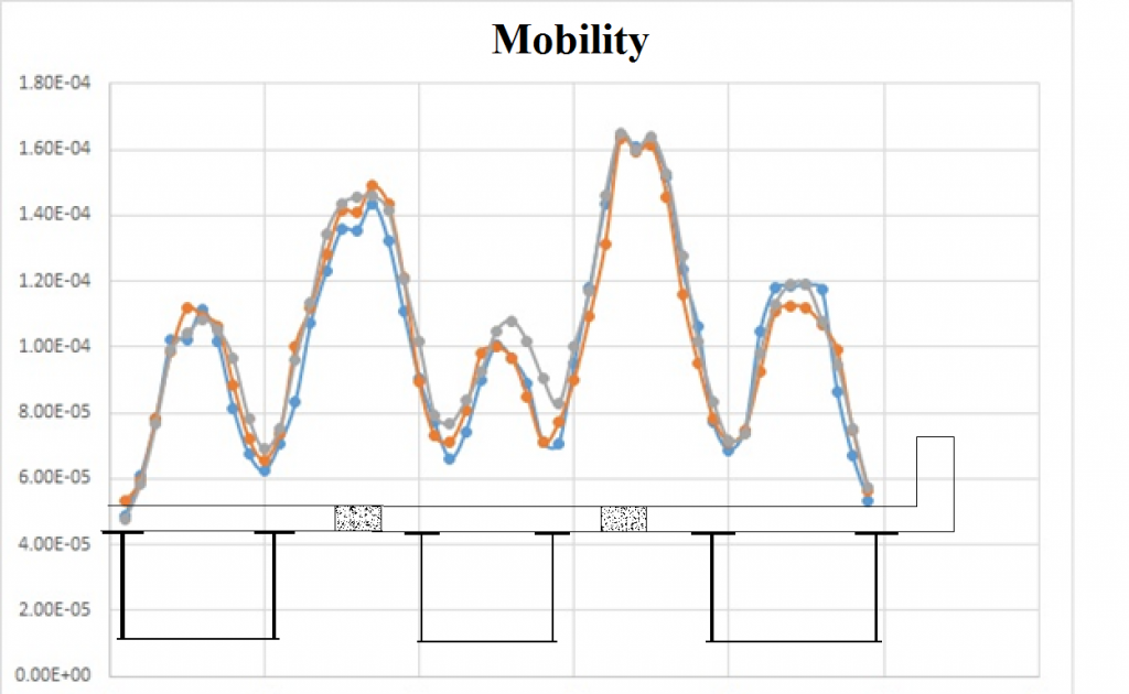
Figure 2. 2-D Mobility Plot, near middle of North span, with high density point layout.

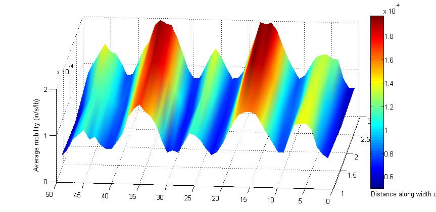
Figure 3. 3-D Mobility Plot of the bridge A.

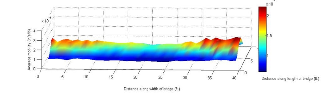
Fig. 4. 3-D Mobility Plot of the longitudinal closure pour of bridge A.
Bridge B Results:


Figure 5. Node Location on the section of the bridge B.

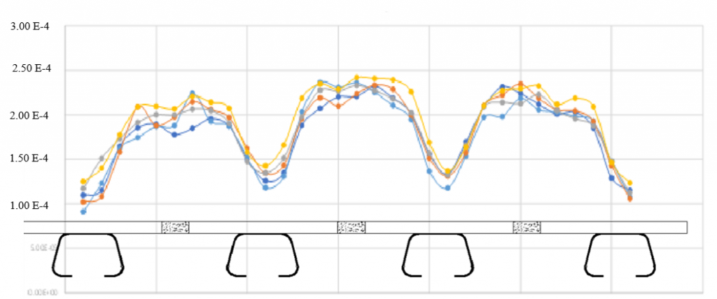
Figure 6. 2-D Mobility Plot of the bridge B.
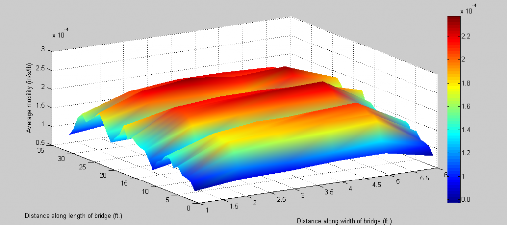

Figure 7. 3-D Mobility Plot of the bridge B.
The second phase of the study includes construction of test specimens at the Structures Lab at FIU. The specimens are currently under construction, and will consist of 3 different specimens, each 15 feet long. The bridge girders are spaced 6 feet apart, and are WF 30 x 99 steel sections. Nelson studs are welded to the top flange. The girders are set on top of concrete jersey traffic barricades, and will rest on elastomeric pads. Each specimen will have a different closure pour detail constructed. This will include the 2 details discussed above, and the third will have a closure pour about 3 feet wide. This third detail is modeled after closure pour details implemented in the MASS 14 projects.
The test specimens should be complete by early summer 2015. IR testing of the specimens will commence. A second set of field testing is envisioned, to obtain IR testing on one or more of the MASS 14 bridges, or bridges with a similar closure pour detail.

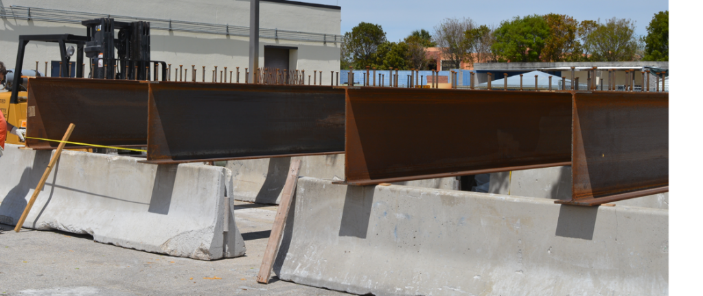
Figure 8. Laboratory test specimens under construction.
Construction of the lab specimens will permit inclusion of simulated cracks, de-bonding and missing (or corroded) reinforcing steel. Current plans are to include the following features in each section.
- a short section with a transverse discontinuity;
- a discontinuity at the joint between the closure pour and the adjacent deck; and,
- a short section where the reinforcing steel is not continued through the joint between the deck and the closure pour.

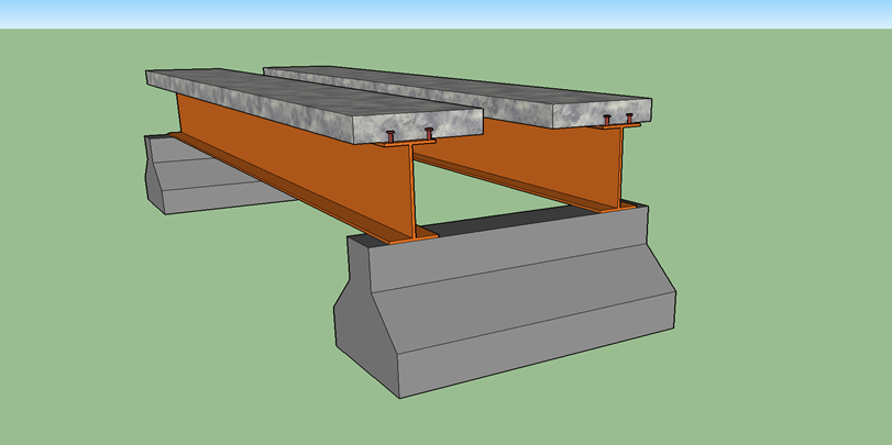
Figure 9. Test specimens prior to installation of closure pour.
Closure pour details for the test specimens will include:
- An 8-inch wide closure pour with hairpin shaped reinforcing bars forming overlapping loops in the closure pour. Longitudinal bars will then extend through the loops. The pour will consist of ultra-high performance concrete. (UHPC). This is similar to the detail in Bridge B.

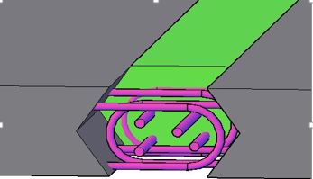
Figure 10. Closure pour detail with hairpin reinforcing and UHPC.
- A 12-inch wide pour reinforced with headed rebars extending into the closure pour. The concrete strength will match the concrete in the adjacent deck section. This is similar to the detail in Bridge A.

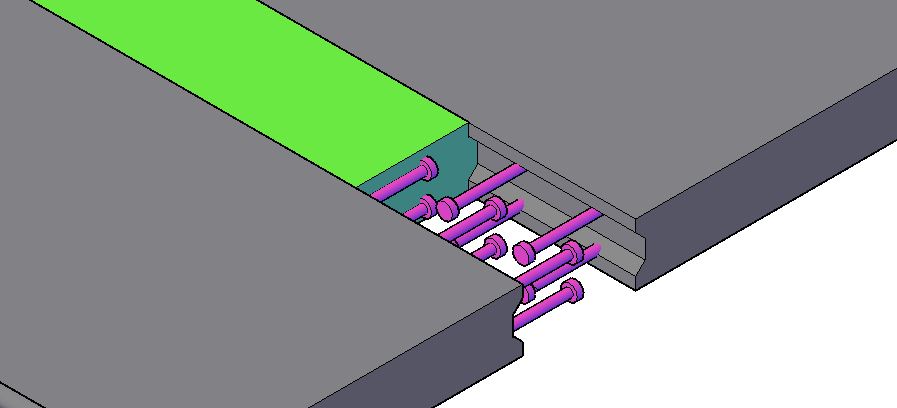
Figure 11. Closure pour detail with headed reinforcing steel.
- A 3-foot wide closure pour with standard overlapped reinforcing bars. The concrete strength will match the concrete in the adjacent deck section. This is similar to the closure pour detail constructed in the MASS 14 projects in Massachusetts. Analytical studies, including finite element modeling is also being performed to validate the IR data and to develop methods to interpret the IR data. The plot below shows how the field IR data was normalized with mobility values from the FEM modeling.

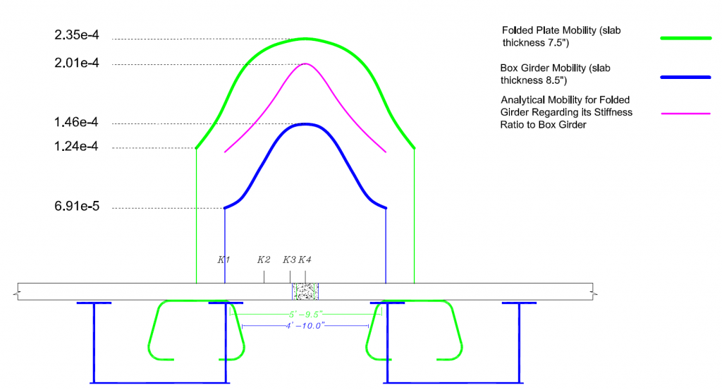
Figure 12. Normalized Mobility Results.

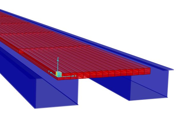
Figure 13. Finite Element Model for Bridge A.

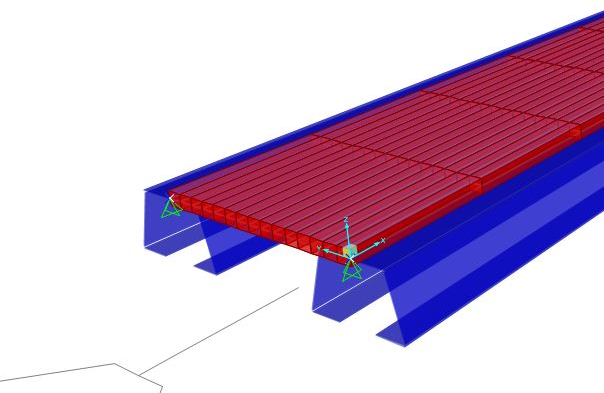
Figure 14 Finite Model of Bridge B, with folded plate girders.
The initial results of the IR testing show promise, as the mobility values reflect expectations. It was expected that mobility values will increase with distance from supporting girders and bents. The normalized plots show this effectively. The 2-D plots also show some variations to the smoother curves in the normalized plots. This may be areas where the reinforcing steel is overlapping. As testing with the laboratory specimens continues, IR testing may be able to identify issues such as cracking, de-bonding, and loss of reinforcing steel due to corrosion. IR testing is known to be able to assist in defining limits of delamination of concrete slabs.
Developing IR signatures for a variety of closure pours and manufactured discontinuities will also provide insight for IR testing to become a common structural condition evaluation tool. This evaluation will provide insight to the behavior of closure pours.
Evaluation of the IR testing results will be incorporated into the Guide. Service life recommendations resulting from the IR test results will also be included.
Task 5 – Development of Framework for Service Life Design
Closure pours are just one of the details identified that can reduce service life. Another design concept that is gaining acceptance is integral abutment bridges. While the elimination of bearings and expansion joints will increase service life and reduce maintenance costs, the integral abutment will introduce other service life impacts. Another phase of development of the manual will study integral abutments and associated service life concerns.
The steps to develop a customized manual for the service life design of bridges are outlined in the SHRP 2 R19A report. Identification of the factors that can reduce service life for a given bridge system is integral to the manual development. Mitigation of these factors is then developed. These strategies the lead to multiple solutions.
As development of the manual continues, customized fault trees are being developed, that take the reader through identification of service life factors to mitigation strategies to development of multiple design solutions. The optimal solution is then selected through life cycle cost analysis.
The efforts performed to date are a subset of effort needed to identify the various factors impacting the service life of bridges constructed with the ABC philosophy.
Task 6 – Development of Tools to Navigate through the Document
No progress has been accomplished for this task.
Task 7 – Technology Transfer
Technology transfer will be accomplished by sharing the information with State DOTs; placing deliverables on the ABC-UTC web site; announcing the deliverables and their capabilities during ABC-UTC webinars; and presenting the completed and ongoing work in conferences, AASHTO meetings and workshops.
Task 8 – Final Report
Results of study are being documented. Compilation of these reports will form the final report.