

Task 1 – Conduct a national literature search to review all bridge railing (cast-in-place and prefabricated railings) designs and details including anchorage systems that have been crash tested for use on the national highway system by state DOTs and private agencies. Survey state DOTs to determine their needs related to prefabricated bridge railing. Information from research projects through the NCHRP, SHRP2, FHWA, and other national, state, and pooled-fund sponsored research will be reviewed as part of this task. Railing shapes that meet the current MASH requirements will be considered I this task and subsequent tasks. As part of this search, consideration will also be given to the different types of elements used in prefabricated bridges.
There are a few different permanent precast concrete barriers that have been developed with different anchoring methods. Precast barriers are generally categorized by the shape of their profile. The New Jersey shape, the F-shape and the single slope are the three most commonly used precast concrete barrier profiles in the United States.
Common methods for anchoring precast concrete barriers to bridge decks include through-deck bolts and adhesive anchors. With the through-deck anchoring method, a hole is drilled through the entire bridge deck and a bolt is inserted through both the barrier and the deck. It is secured with heavy washers and nuts on both ends of the steel bolt. One issue with this design is getting access to the underside of the bridge to secure the nut. Another issue is weathering of the exposed connection. Figure 1 shows a typical anchoring detail for the through-deck configuration.

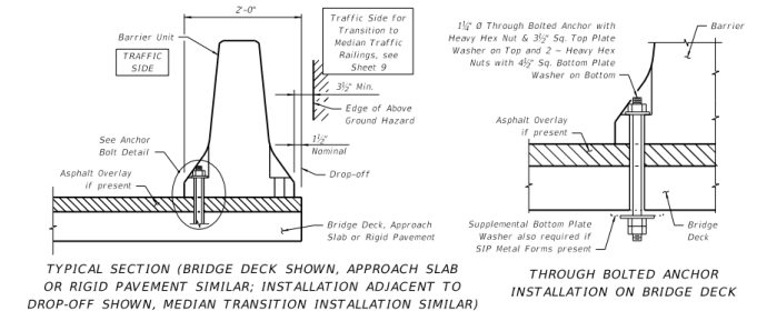
Figure 1 – Through-Deck Bolting Detail (Source: FL DOT 414)
A different way of connecting a barrier with the through-deck method is by pretensioned rods that are inserted all the way through the wall and the deck slab. They are then anchored to the bridge deck by end plates, washer, and nuts. An example of this can be seen in Figure 2.

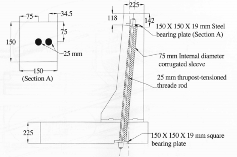
Figure 2 – Barrier to deck Slab Connection (Source: Patel Dissertation, Fig 3.1)
Another precast concrete barrier anchoring technique that is used is an adhesive-bonded anchor. This method is completed by drilling a hole into the bridge deck and then inserted the threaded bolt through the barrier and into the deck. The bolt is then secured with an adhesive. This method can be seen in Figure 3. One issue with this anchoring method is the strength of the adhesive used.

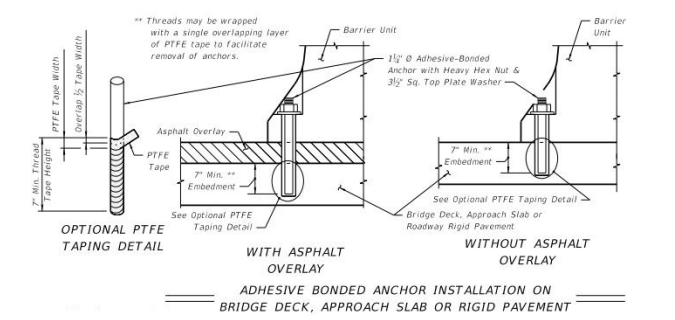
Figure 3 – Adhesive-bonded Anchor Detail (Source: FL DOT 414)
A precast barrier wall system similar to the adhesive anchored connection is engineering and patented by Clampcrete. It has been crash tested and approved for use. It is connected to the bridge deck by polyester resin anchors that are drilled into the bridge deck. This system is shown in Figure 4.

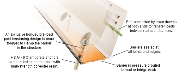
Figure 4 Clampcrete Barrier System (Source: clampcrete.com)
Task 2 – Based upon the results of the literature search, the research team will develop conceptual prefabricated railings with associated anchorage systems and details. Although the ultimate goal is to develop a system that can be adopted for multiple railing shapes, only one shape will be utilized in the experimental program to be conducted in Task 3. At a minimum, the concepts will consist of details for connecting the rails to the deck and for connecting adjacent rails. It is anticipated that a minimum of three different rail-to-deck and three different rail-to-rail systems will be conceptualized.
For this project, based on a nationally conducted survey, an F-shape profile was chosen. When connecting the precast concrete barrier to the bridge deck, two connection concepts were designed. The first design concept includes a u-shaped rebar that is inserted through the bottom of the bridge deck and into the barrier segment. The u-shaped rebar will then be secured with 10 ksi, non-shrink, fiber grout. This concept can be seen in Figure 5.

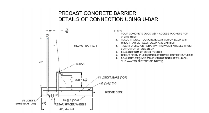
Figure 5 – Details of Connection using U-bar
Another concept consists of an inclined stainless steel bar and bar splicer. The bar splicer will be precast into the bridge deck. Then the stainless steel bar will be inserted into the barrier segment and threaded into the bar splicer. This connection will also be sealed with grout and is shown in Figure 6.

Figure 6 – Details of Connection using Stainless Steel Bar with Threaded End and Bar Splicer
The barrier-to-barrier connection detail includes four headed rods precast into the end of the barrier segment. The headed rods are inserted into a pocket in the adjacent barrier. Figure 7 shows this detail. Also, more detailed drawings of the barrier test concepts are included at the end of this report.

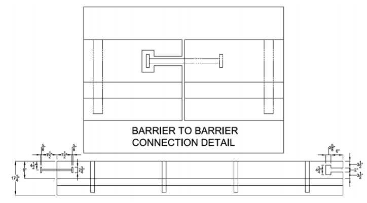
Figure 7 – Barrier Connection Detail
The test level 4 design load of 54 kips was used to design the connections. To limit the damage to the barrier and bridge deck, the connections were designed to allow the connections to fail instead of the barrier and bridge deck.
Task 3 – By combining the various connection systems together, a total of nine combinations can be realized. These nine combinations will be narrowed to the five most promising. These systems will then be tested in the laboratory with a pendulum-type testing apparatus. The systems will be evaluated based upon how they impact their individual strengths and how they impacted the performance of the deck overhangs used to support the railing.
The test plan will include static testing of the two barrier system concepts shown above. Each segment is 12 feet in length. A hydraulic actuator will apply the loads cyclically. The actuator that will be used in shown in Figure 8.

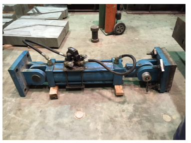
Figure 8 – Hydraulic Actuator
The barrier segments will be tested individually to test the barrier to deck connection. Then they will be connected and tested again. The force will be applied at the joint to measure the force distribution. A schematic drawing of the lab test set-up can be seen in Figures 9 and 10.

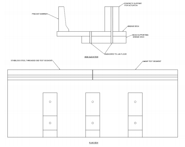
Figure 9 – Lab Test Set-up

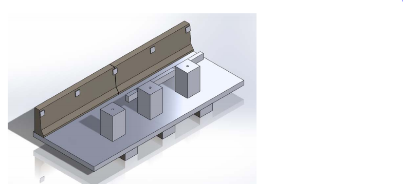
Figure 10 – 3D Model of Lab Set-up with Applied Load Locations
The hydraulic actuator will be mounted on the beam to apply load along the precast barrier segments. A ponding test will also be conducted on the connections to test for durability. Testing is anticipated to begin in the summer of 2015.
Task 4 – A final report will be developed that documents the entire project with a special emphasis on the results of Task 3. More importantly, recommendations for rails on which full-scale crash testing should be conducted will be made. If appropriate, the research team will make recommendations for potential modifications to the details.
The final report is anticipated to be submitted December of 2015.