

Task 1 – A detailed review of scientific papers focusing on previous uses of grouted couplers, and integral abutments, in ABC projects. In addition, all relevant developments and design details/requirements for integral abutments used in typical bridge construction.
An extensive literature search has been completed and the findings compiled for inclusion in the report.
Task 2 – Initially, several details for an integral abutment using grouted couplers will be developed for review by the TAC. Building upon comments from the TAC and contractors familiar with ABC practices/projects, these conceptual designs will be refined, modified and/or eliminated, if needed. Once final designs of the conceptual integral abutment details are drafted, the TAC committee will select one or two of the most promising concepts for evaluation and testing in the laboratory, see Task 3.
Several integral abutment (I-A) connection details utilizing grouted rebar couplers were designed and proposed to the TAC. Based on previous experience by the research team using these types of couplers/connections and discussions with the TAC regarding constructability within the realm of ABC, it was decided that in addition to a grouted coupler I-A connection, that it would also be valuable to evaluate a alternative I-A connection detail. This details was developed by the research team, and though it does not incorporate grouted rebar couplers, it aims to drastically improve constructability. Final design details were then drafted, presented to the TAC and approved for construction of test specimen.
Task 3 – The integral abutment detail(s) selected in Task 2 will be fabricated in the laboratory for full-scale testing and evaluation. Laboratory testing will resolve to determine the following: 1) constructability (tolerance) issues, if any, related to the integral abutment joint construction and use of the grouted couplers, 2) the structural performance of the integral abutment detail in terms of strength, and 3) the structural performance of the integral abutment detail in terms of durability.
Based on the results of Task 2 and the budget constraints, three I-A details carried forward for laboratory construction and testing: 1) typical cast-in-place (CIP) I-A detail for Iowa (Fig. 1), 2) I-A connection utilizing grouted couplers (Fig. 2), and 3) the I-A connection developed by the research team (Fig. 3), the HP coupled connection.

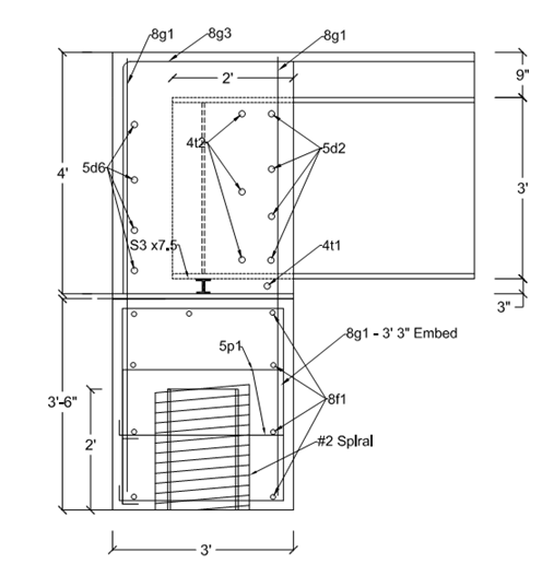
Figure 1. Specimen 1 – Iowa DOT cast-in-place integral abutment detail

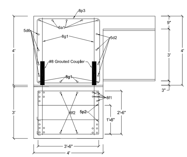
Figure 2. Specimen 2 – Integral abutment connection detail utilizing grouted rebar couplers

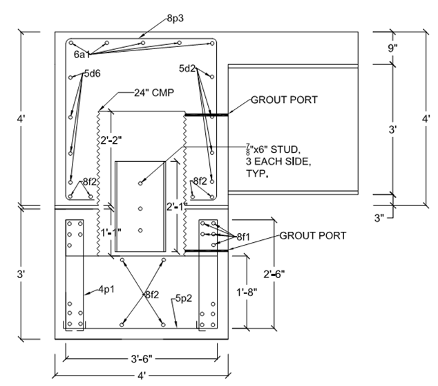
Figure 3. Specimen 3 – Integral abutment connection detail using CMP voids and steel HP coupler
Currently, all three specimen are in the fabrication/testing phase in the laboratory. The CIP specimen is cast, and currently being instrumented for testing in the coming weeks, see Fig. 4. The grouted coupler specimen is cast and awaiting grouting of the grout bed and the couplers, see Fig. 5; it will be load tested following curing of the grout. Lastly, the HP coupled specimen has the pile cap section cast, see Fig. 6, and forming of the abutment diaphragm is ongoing, see Fig. 7.

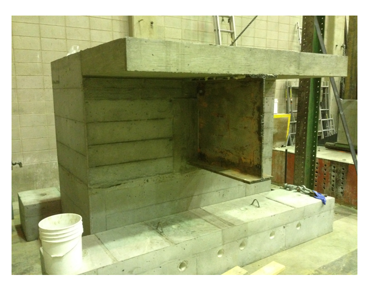
Figure 4. CIP integral abutment specimen in preparation for load testing

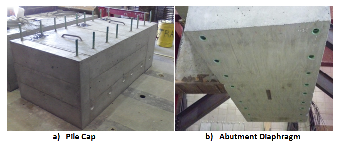
Figure 5. Grouted coupler specimen prior to grouting

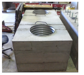
Figure 6. Pile cap section of the HP coupled specimen after casting

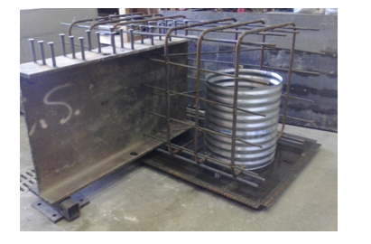
Figure 7. Abutment diaphragm section of the HP coupled specimen during fabrication
Illustrated in Fig. 8 is the proposed connection process for the HP coupled section. After the abutment diaphragm section is in place on top of the pile cap, likely via sliding, the 2 ft length of HP recessed within the abutment diaphragm void will be lowered so that half of the HP is in the pile cap and the other half remains in the abutment diaphragm. The CMP voids will then be filled, either with self-consolidating concrete (SCC) or grout.

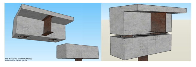
Figure 8. Connection of the HP coupled specimen
Lastly, Fig. 9 illustrates the test setup for testing of the three I-A specimen. Anchor blocks will be tied to the strong floor on either side of the pile cap, and then the pile cap will be post-tensioned to the anchor blocks to create a fixed connection. Hydraulic cylinders will then apply a load at the end of the girder/deck, one horizontally to simulate thermal loads, and the other vertically to simulate live loads.

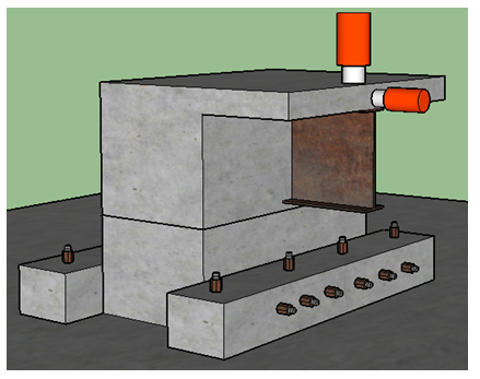
Figure 9. Laboratory test setup for the three integral abutment specimen
Task 4 – A final report will be developed that documents the entire project with a special emphasis on the results of Task 3. More importantly, recommendations for integral abutment details using grouted coupler connections for use in ABC projects will be made.
Results of study are being documented. Compilation of these reports will form the final report.