

Task 1: Develop ideas on types of details that could be used to join the girder ends over the pier and develop a frame action.
A series of detail analysis were carried out to establish the demand side of design. By demand it is meant to comprehend the type of forces that connection over the middle supports will be subjected to. In the case of non-seismic application, the connection over the middle supports are mainly subjected to negative moment. i.e. the bottom flanges of the girders transfer, mainly compressive force into concrete diaphragm. Therefore the bottom flanges of the girder inside the concrete diaphragm does not need to be positively connected and type of detail used in non-seismic regions shown in Figure 1 are sufficient.

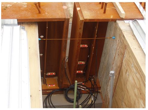
Figure 1. Detail used in Non-Seismic regions
However, in the case of seismic application it was determined that the bridge girders over the middle support could very well be subjected to positive moment. i.e. bottom flanges will be subjected to tension and try to pull out of the concrete diaphragm. Figure 2 shows an example of moment envelop diagram that was developed by conducting linear dynamin time history analysis.
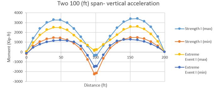

Figure 2- Moment envelop diagram showing positive moment over middle support
As it will be described under tasks 2 and 3, it was observed that the detail used in non-seismic application (Figure 1) is not suitable for use in high seismic areas. The modified details that is currently is envisioned is shown in Figure 3. As shown in Figure 3, the connection envisioned is similar to non-seismic detail, except that it uses high strength bolts to positively connect the girder ends. It was also observed that amount of reinforcement in the concrete diaphragm needs to be increased, so that concrete diaphragm remain elastic during entire seismic events.

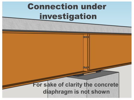
Figure 3- Envisioned connection
Task 2: Modify the existing detailed non-linear finite element models used by the P.I. to study the non-seismic details to determine the force transfer mechanisms of the details identified under Task 1.
As shown n Figure 4, detail non-linear finite element model was developed to:
a)Study the force transfer mechanism for the envisioned connection
b)Numerically identify the modes of failure.
c)Modify the envisioned connection, so that concrete diaphragm remain elastic during major seismic event.

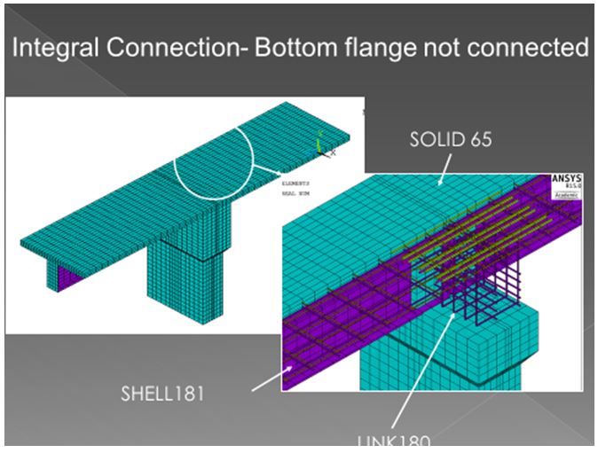
Figure 4- View of model used to conduct non-linear (material and geometrical) finite element analysis
Task 3: Using the non-linear FE model, conduct a parametric study to comprehend, both behavior of the proposed connection detail(s) during seismic event at the macro and micro levels.
Using the model shown under task 2, series of nonlinear analysis were carried out to comprehend:
a)Force transfer mechanism for the envisioned connection detail for seismic areas
b)Numerically identify, as best as possible, the modes of failure.
One of the challenging point in achieving the two objectives listed above was the type of loading that the model should be subjected to. Series of prototype bridges were designed based on Caltran recommended design provisions and were subjected to various ground motions. However, one could question such approach to establish the demand side, as outcome may change based on the details of the prototypes and ground motions used. Therefore it was decided to subject the model to three different types of loading as shown in Figure 5.
It should also be mentioned that the model consists of portion of girders on either side of the concrete diaphragm, equal to distance from middle support to point of inflection.
The three types of loading considered are
a)Pushing down the ends of the girders
b)Pushing up the two ends of the girder
c)Pulling up one end of girder and pushing down the ends of other girder 
Figure 5 – Three loading types used to study behavior of envisioned connection
At this point we are still modifying and further refining the envisioned detail and it is too early to recommend a detail for testing. What we have learned is that, for integral option (where superstructure and substructure are monolithic. Practiced mainly in west coast), significantly more closed stirrups needs to be placed in the concrete diaphragm and further a good connection between super and substructure needs to be developed to prevent early failure of concrete diaphragm when it is subjected to moment reversal.
Task 4: Develop an experimental testing program, capable of verifying the project recommendation in Phase II of the study.
No progress has accomplished for this task
Task 5: A final report
Results of study are being documented. Compilation of these reports will form the final report.